

 Oil service interval reset Audi A4 B8
Preparing to Remove XU10J4/RFY Motor
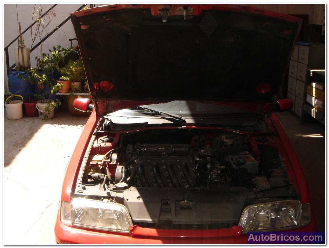
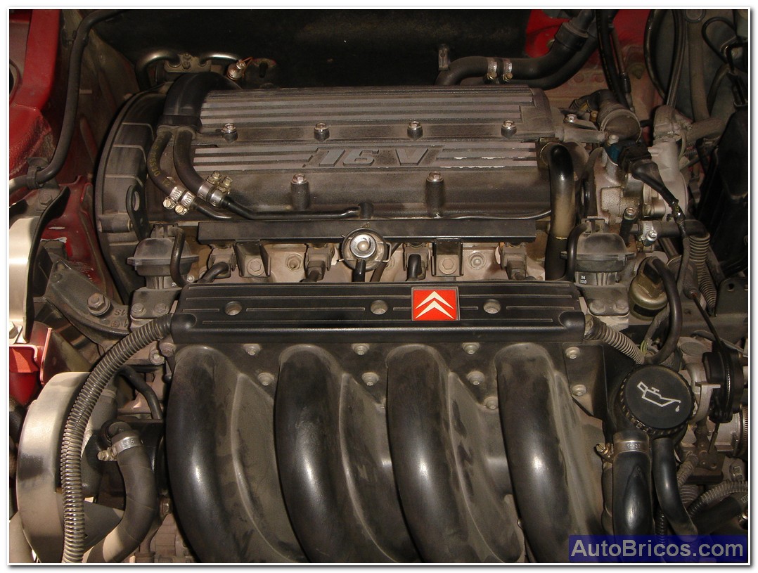
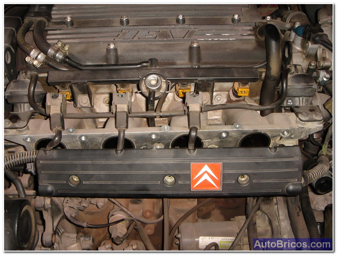
This reportage show the pictures I took in 2008 in the process of disassembling the engine of the Citroen ZX 2.0 16v 155hp (from 1992), this engine is known by the reference: XU10J4/RFY.
This engine usually sweats oil by the gasket head cover, especially because of the passage of time, and depending on mileage also lose their effectiveness leading all seals that prevent oil from leaking out (for example the camshaft in the distribution side, the crankshaft, and also in the cylinder head seals the valve guides.
I finally decided to pull the engine because I had to change a long list of parts, (among others, the complete clutch and the complete distribution including the water pump),
Then show them the photo reportage of the first part of disconnecting, in which I began to prepare the engine and its surroundings for removal:
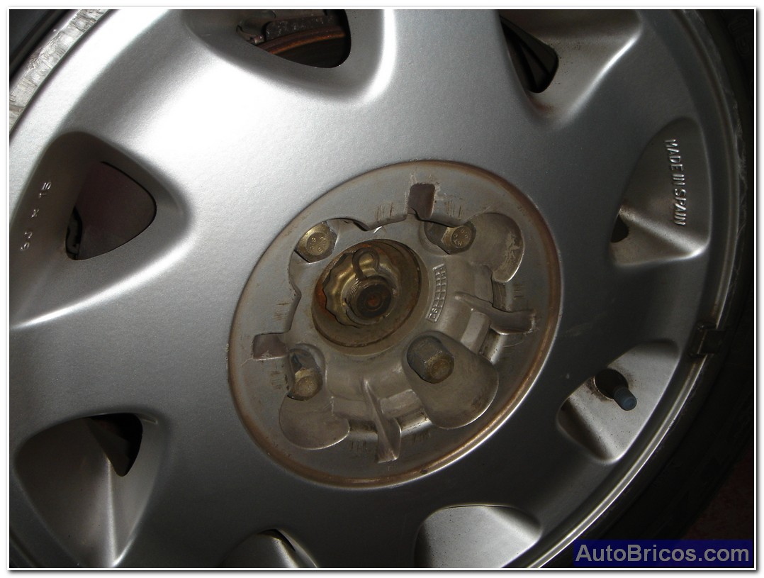
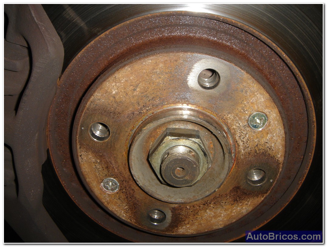
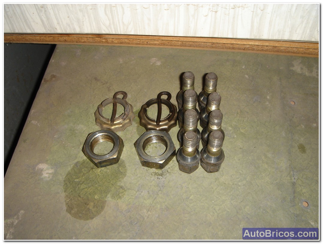
The first step is to make sure we can loosen the nuts of the bearing because otherwise, when we remove the wheels will be difficult to counter; With the car on the ground, handbrake hechado, engine off, and the first gear engaged (to help it does not move when you try to loosen the wheel bearing nut), we can draw the central hub caps and see that there is a metal with a pin that secures the bearing nut to prevent it from unscrewing, remove the pin, we get the metal bowl nut blocks, and we can see the bearing nut, with a good socket wrench and a good lever, trying to loosen the nut; advise to put anti-seize even a day before you do, can be very stuck, do the same with the other wheel. Once removed the 2 nuts of the bearing we can lift the car, remove the 4 screws on each wheel, and remove the drive wheels.
 |
 |
 |
 |
 |
 |
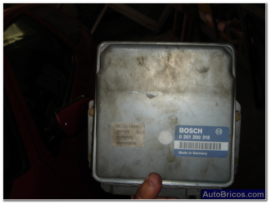
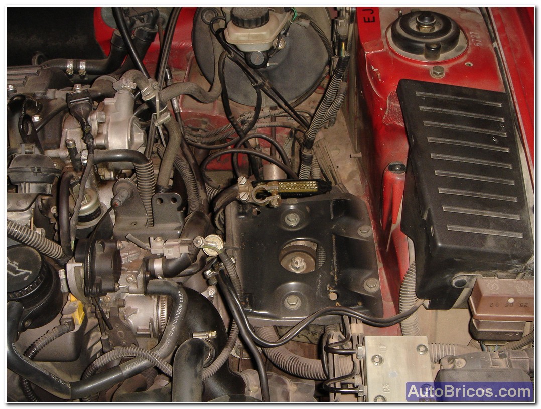
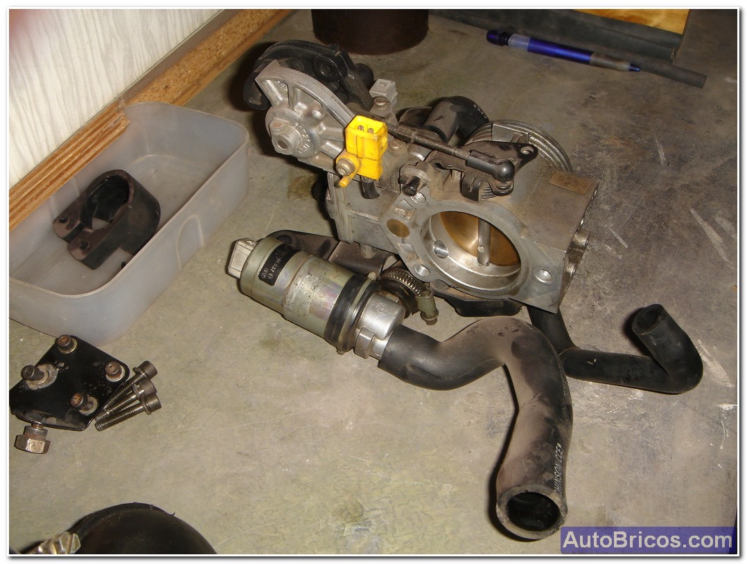
Once lifted the car, we can begin to clear the area where is located the car battery and the admission, We take out the battery, the control unit, which is the Bosch MP3.2 ref. 0261200218 (also carefully disconnect the electrical connector and disconnect also lower hose inlet pressure reading is also at the bottom of the unit. We took also the plastic body that supports the battery. Then we get main suction tube that goes to the intake moth, after we get the block admission moth, and idle controller (pictured is just left of the entrance wing.
 |
 |
 |
 |
 |
 |
 |
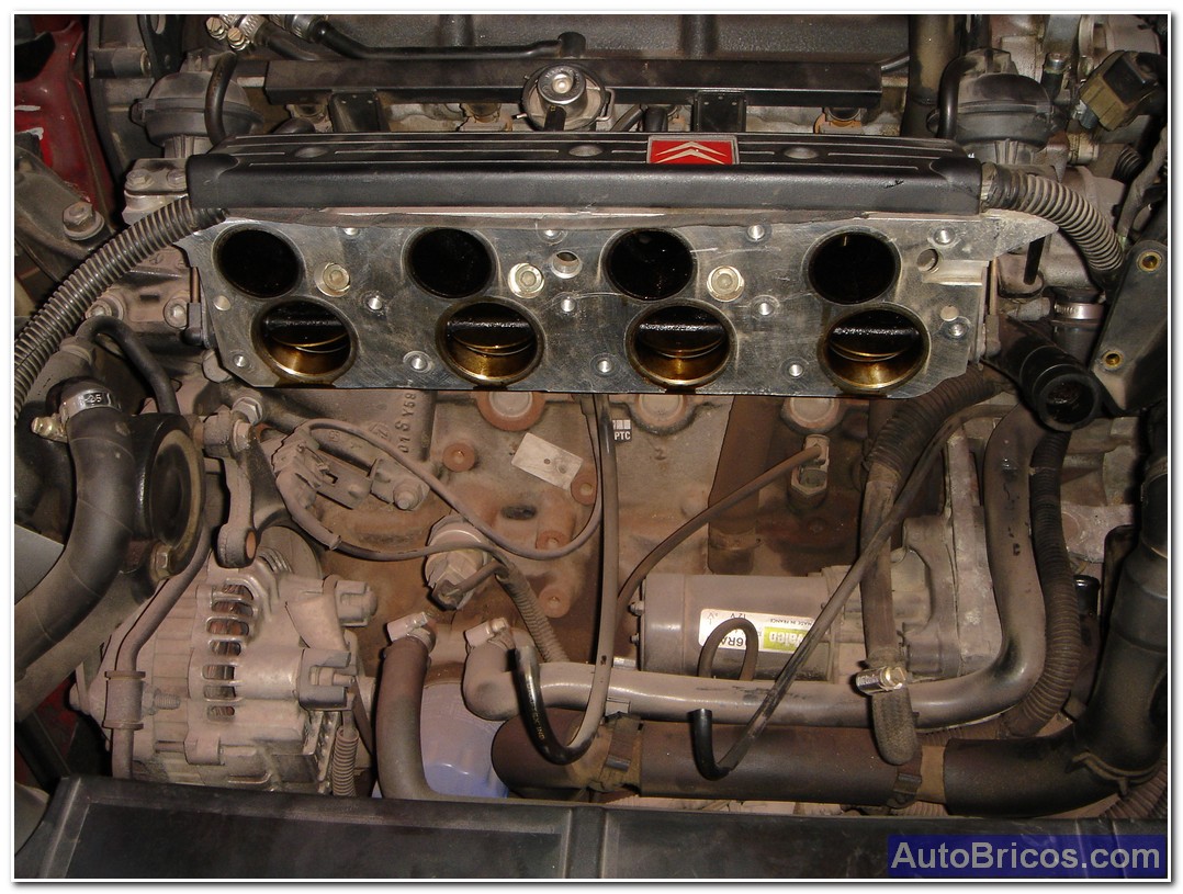
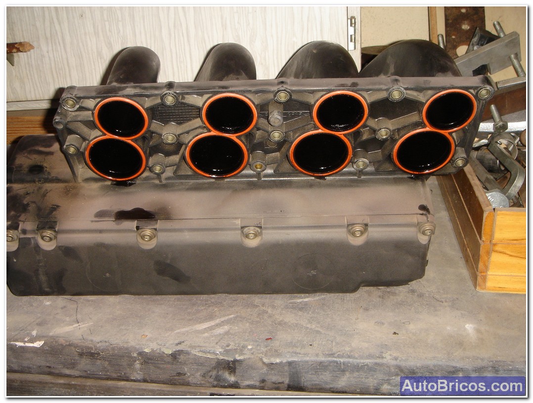
Now that the area is more clear, we can get the intake manifold (which is black plastic).
 |
 |
 |
Then we can clear the lower area where the air filter box, we can electrically disconnect all injectors.
 |
 |
 |
 |
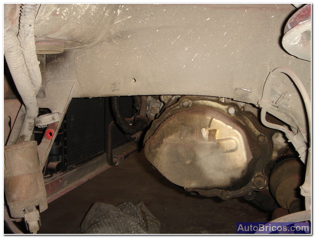
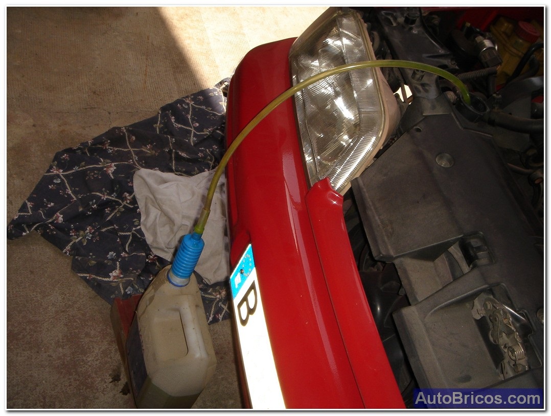
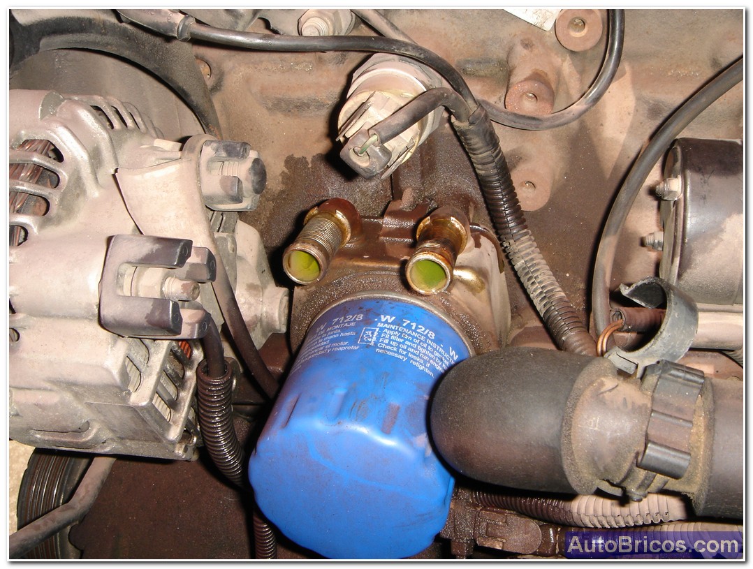
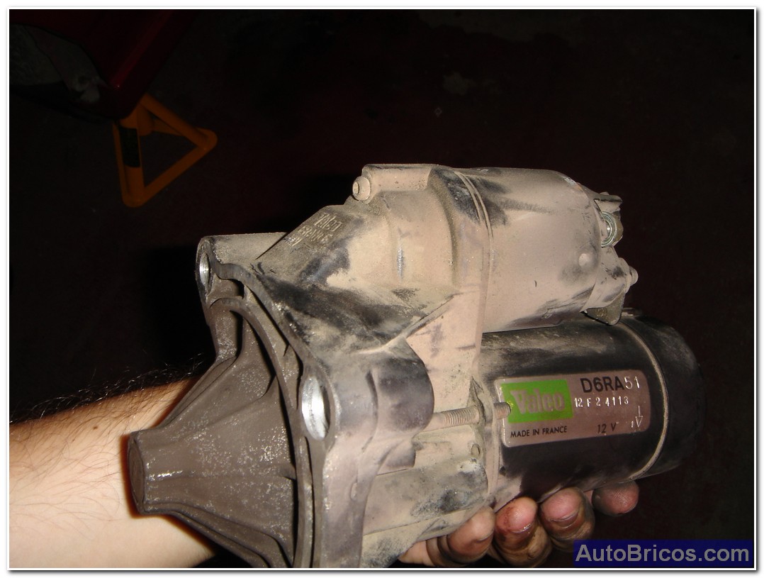
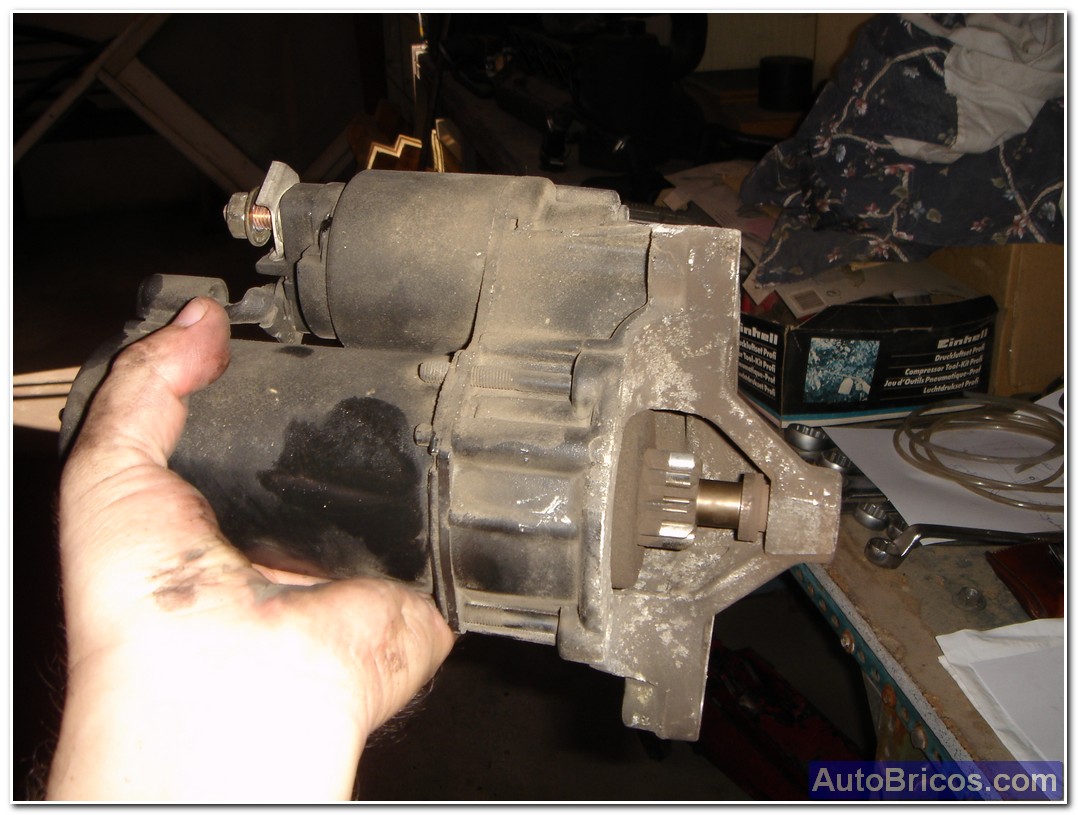
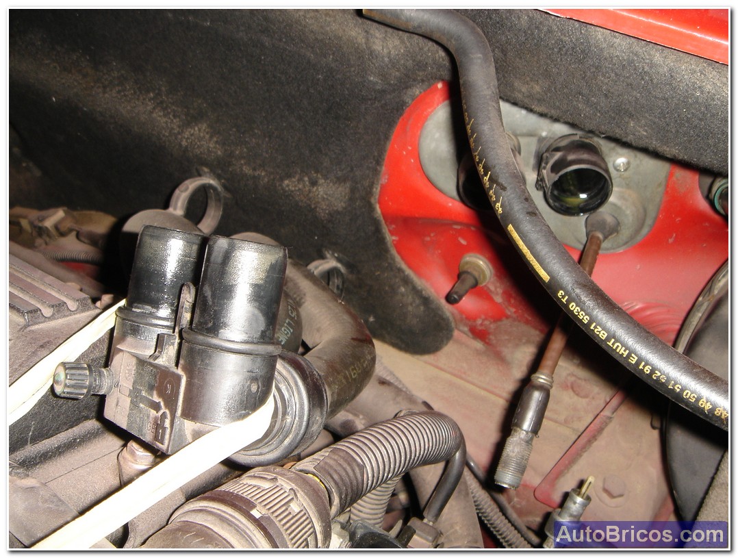
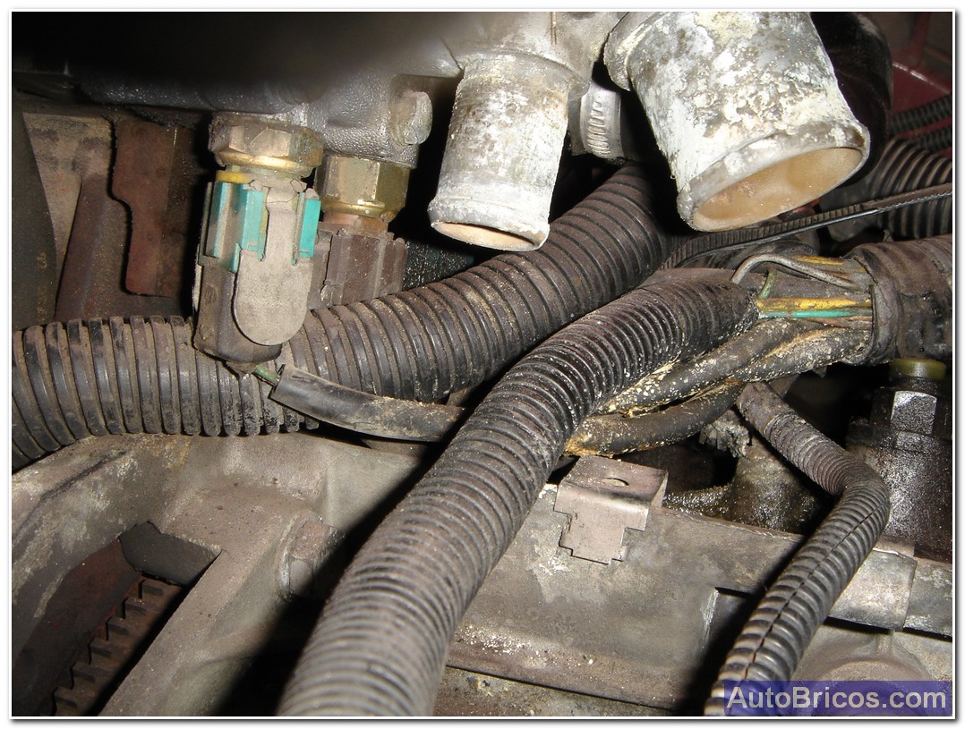
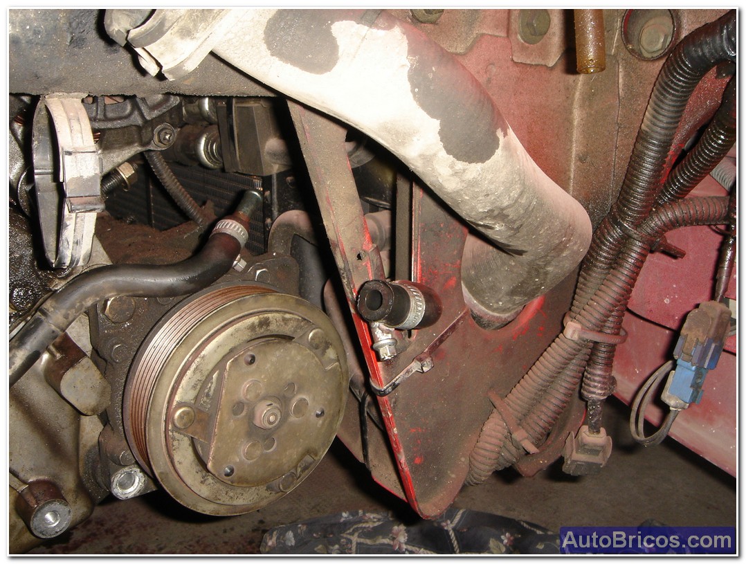
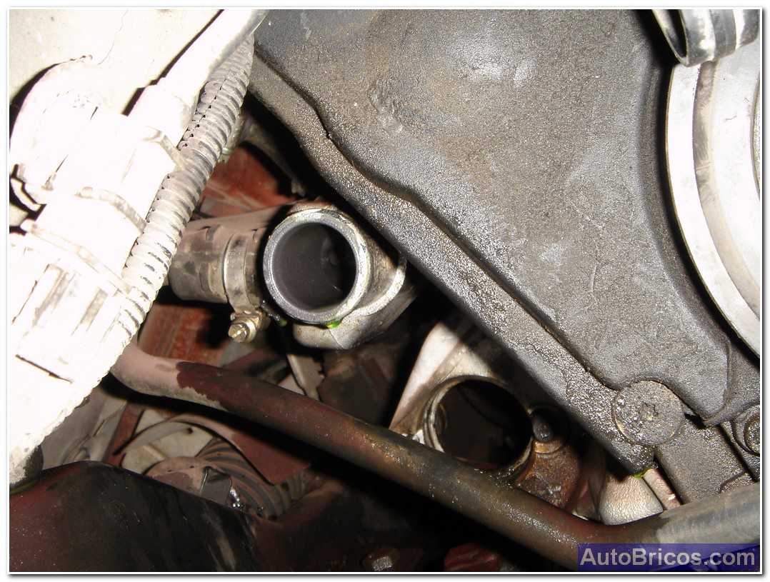
In my case I chose to clear the front of the engine so that it can handle better then the crane, so I drained the cooling system radiator cap and pulled the remaining cooling hoses at the front of the engine. To continue clearing the step motor and have a look at the whole flywheel + clutch, I decided to take the starter too. Electrically also going removing all electrical connectors of different devices and engine sensors to isolate the engine harness.
 |
 |
 |
 |
 |
Decouple the cable also clutch actuation.
 |
 |
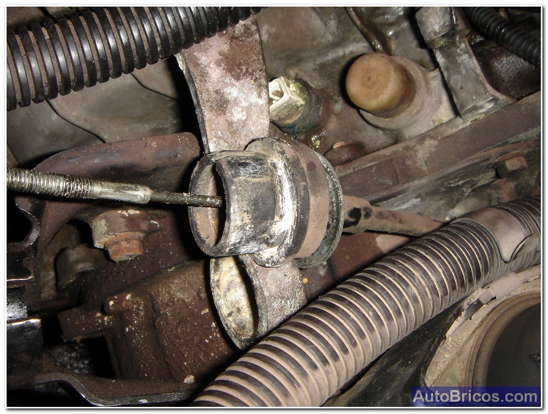 |
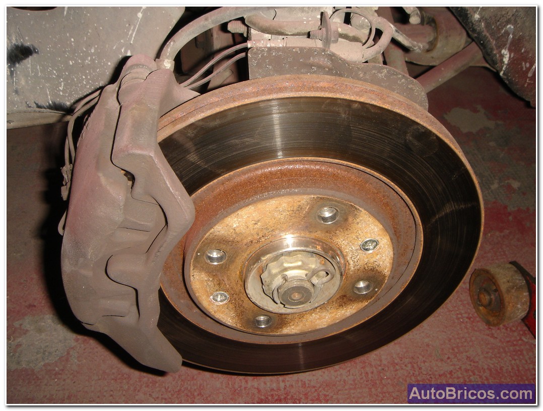
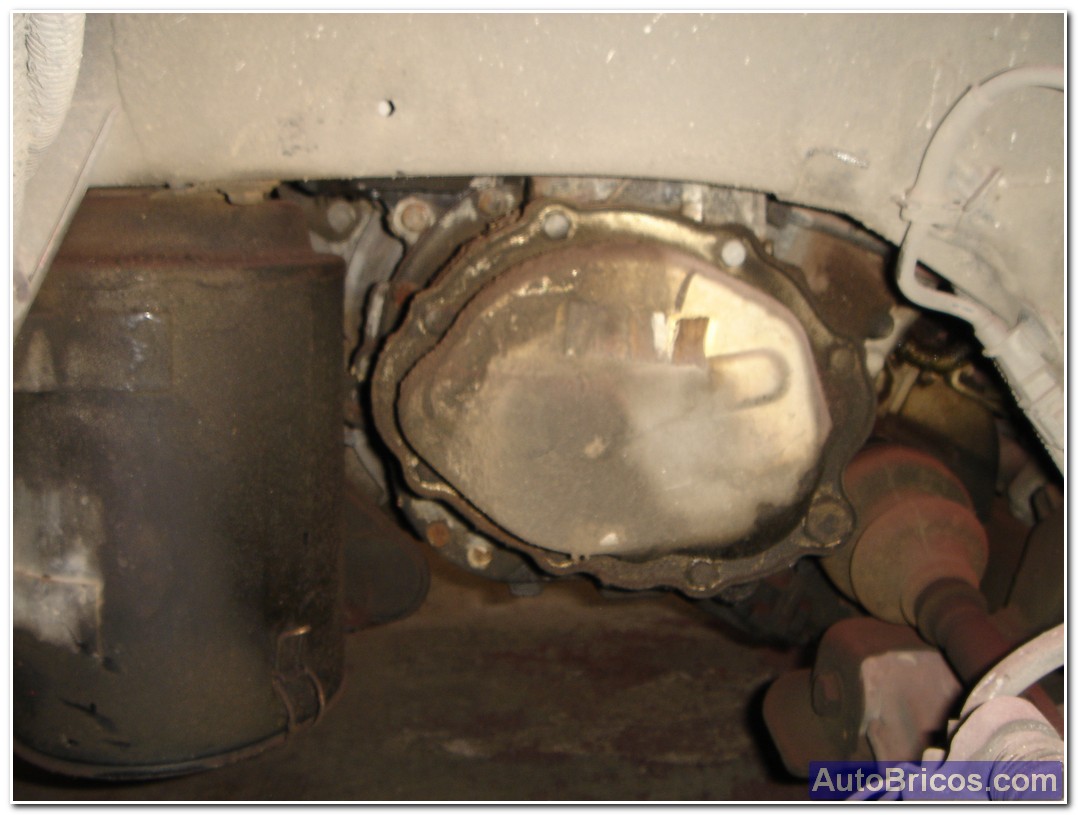
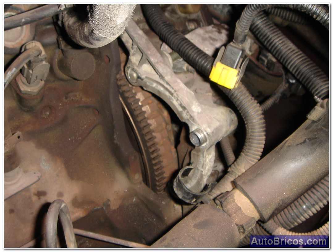
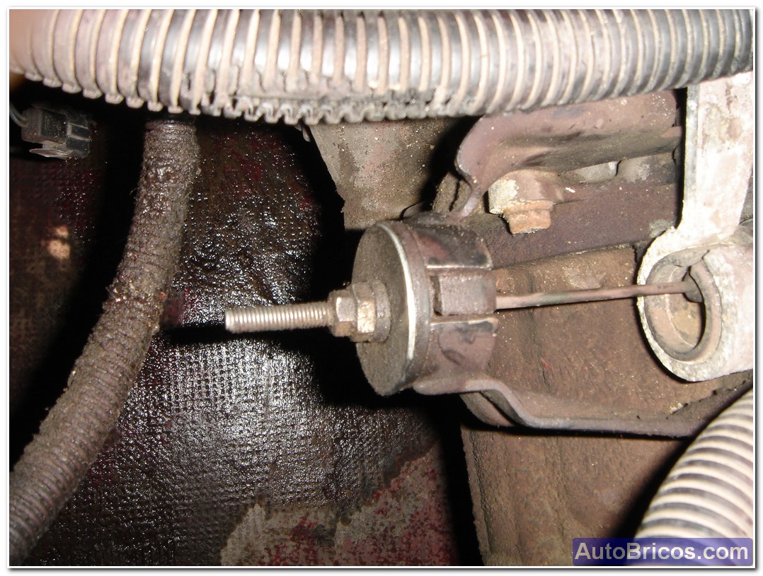
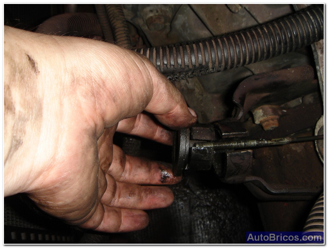
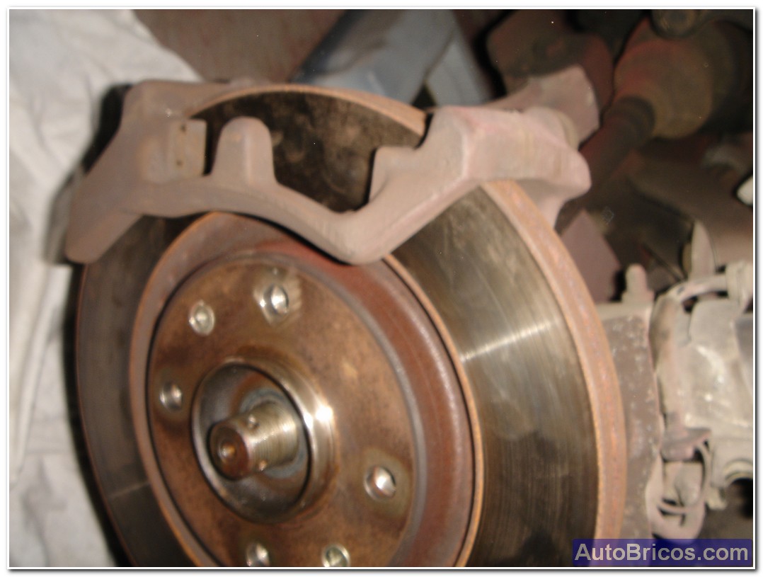
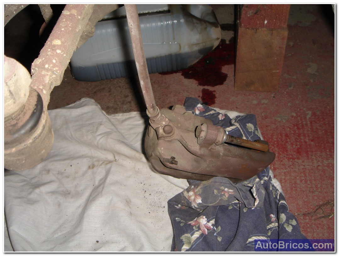
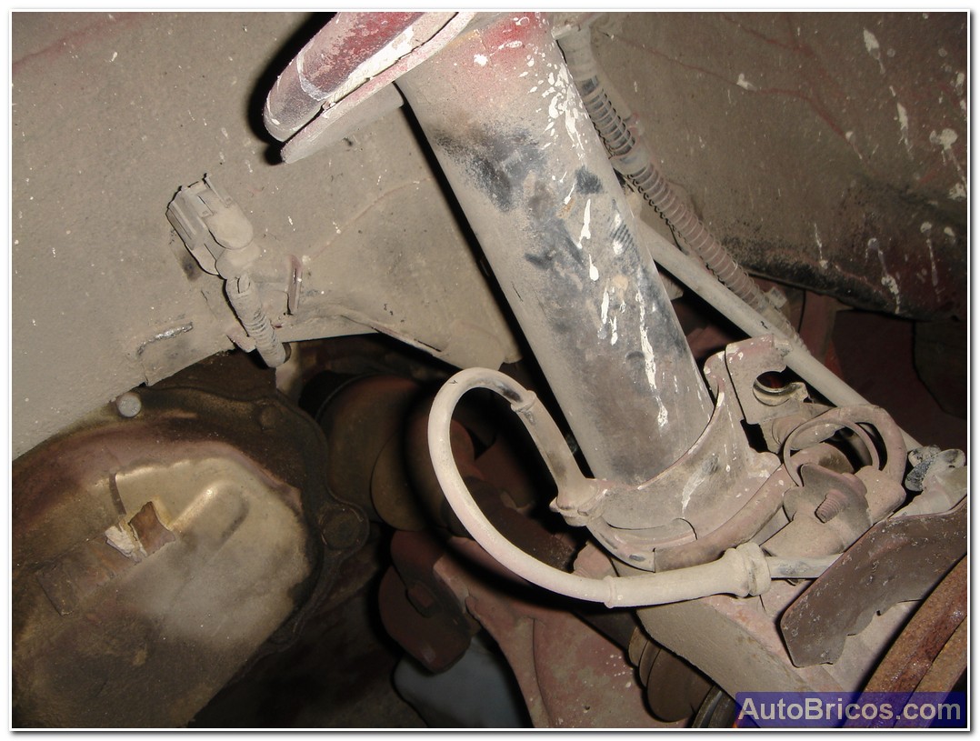
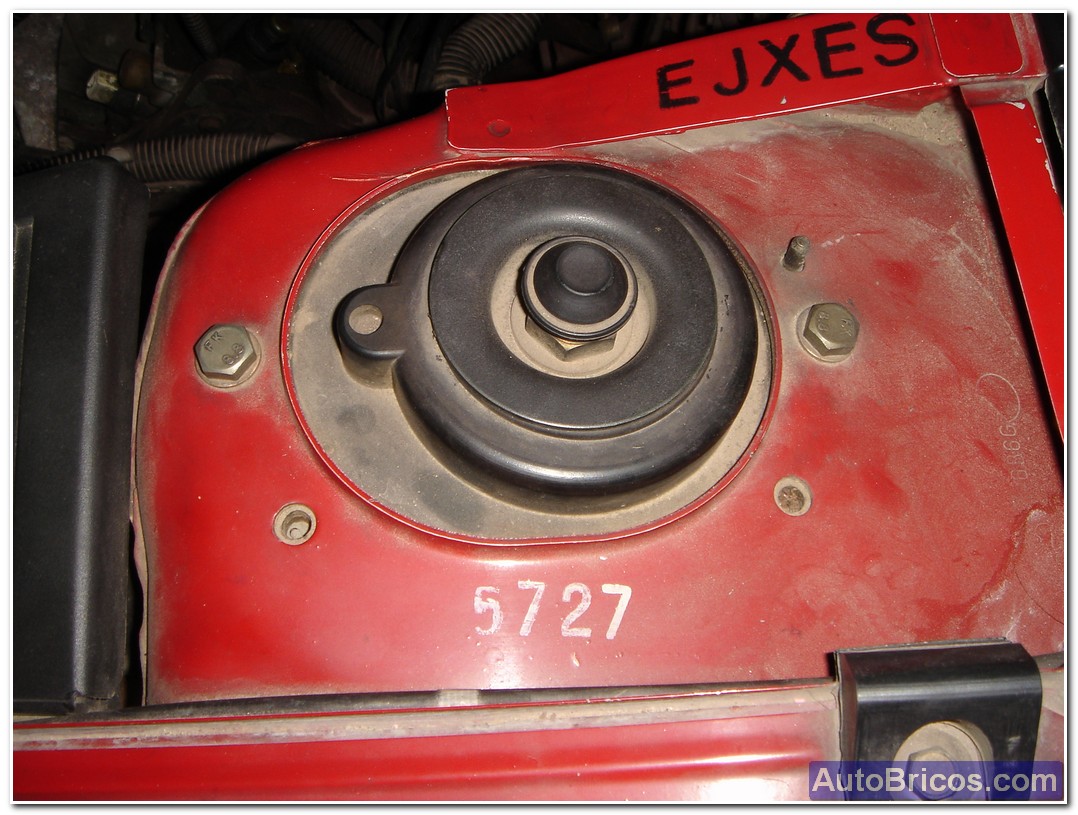
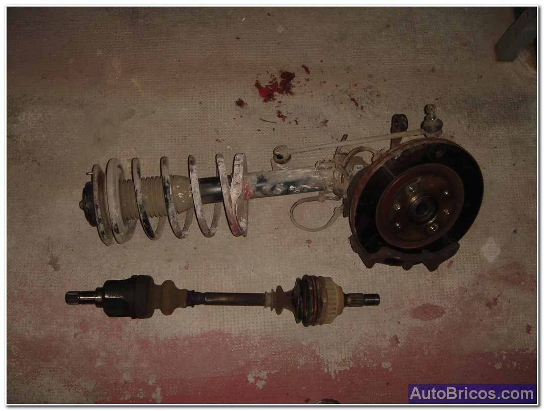
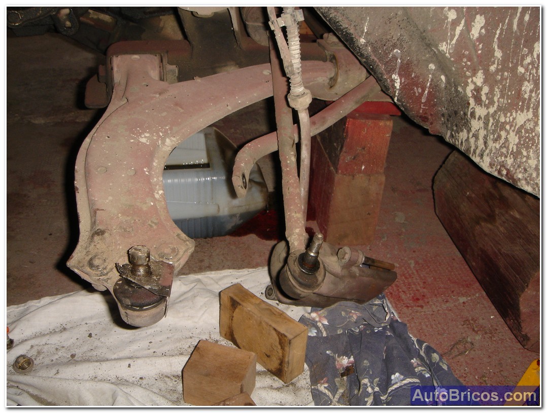
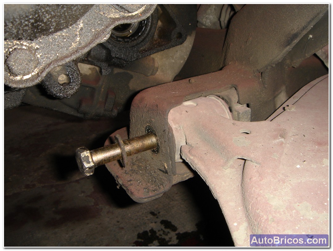
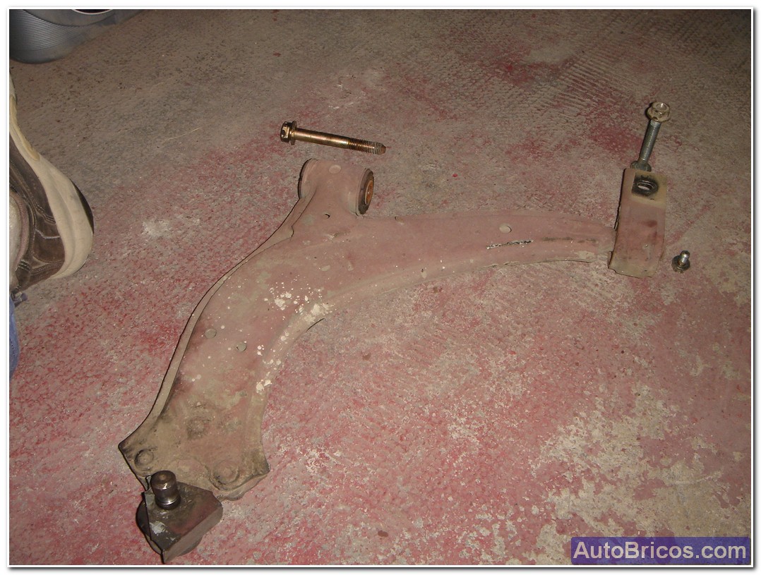
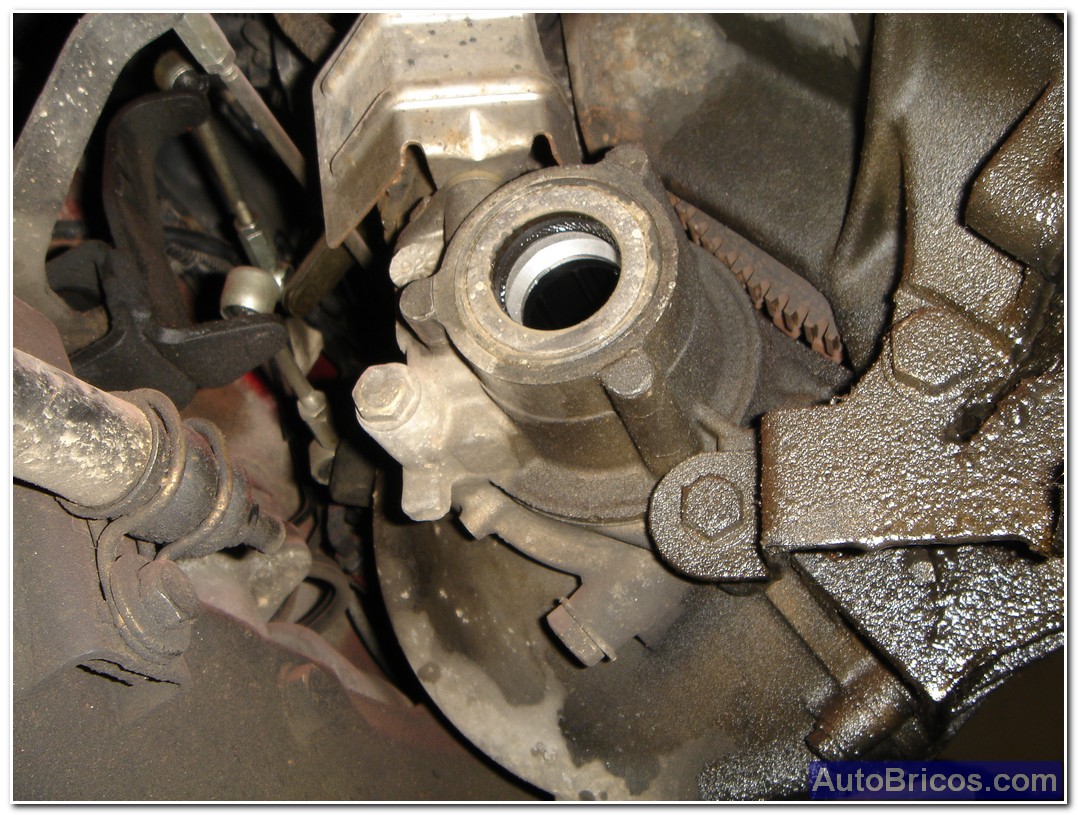
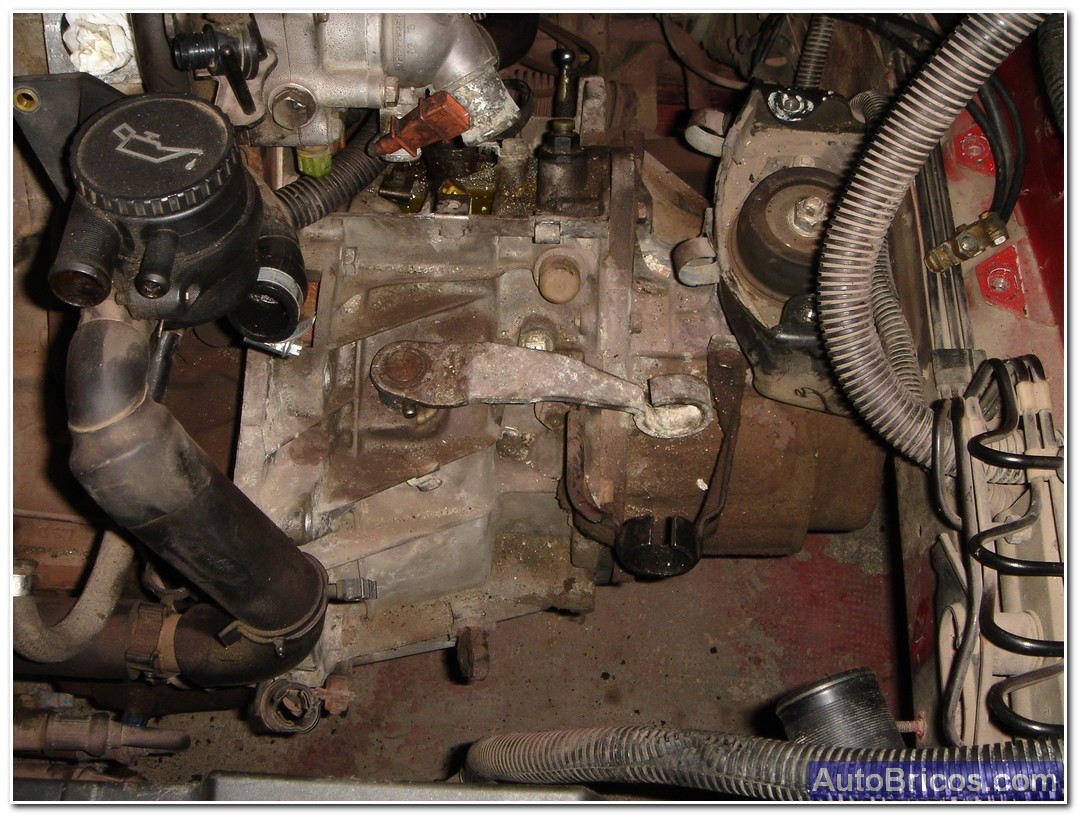
At this point the idea was to remove the bearings, and for this we must decouple the bottom of the knuckle joint and have more accessibility, turrets also decided to remove buffer, decoupling also the brake calipers, with that the wheel arch would fully accessible for better handling engine for extraction. Keep in mind that you have to empty the box valvulina changes but will spill when removing the bearings and lose losing seal retainers.
 |
 |
 |
 |
 |
 |
 |
 |
 |
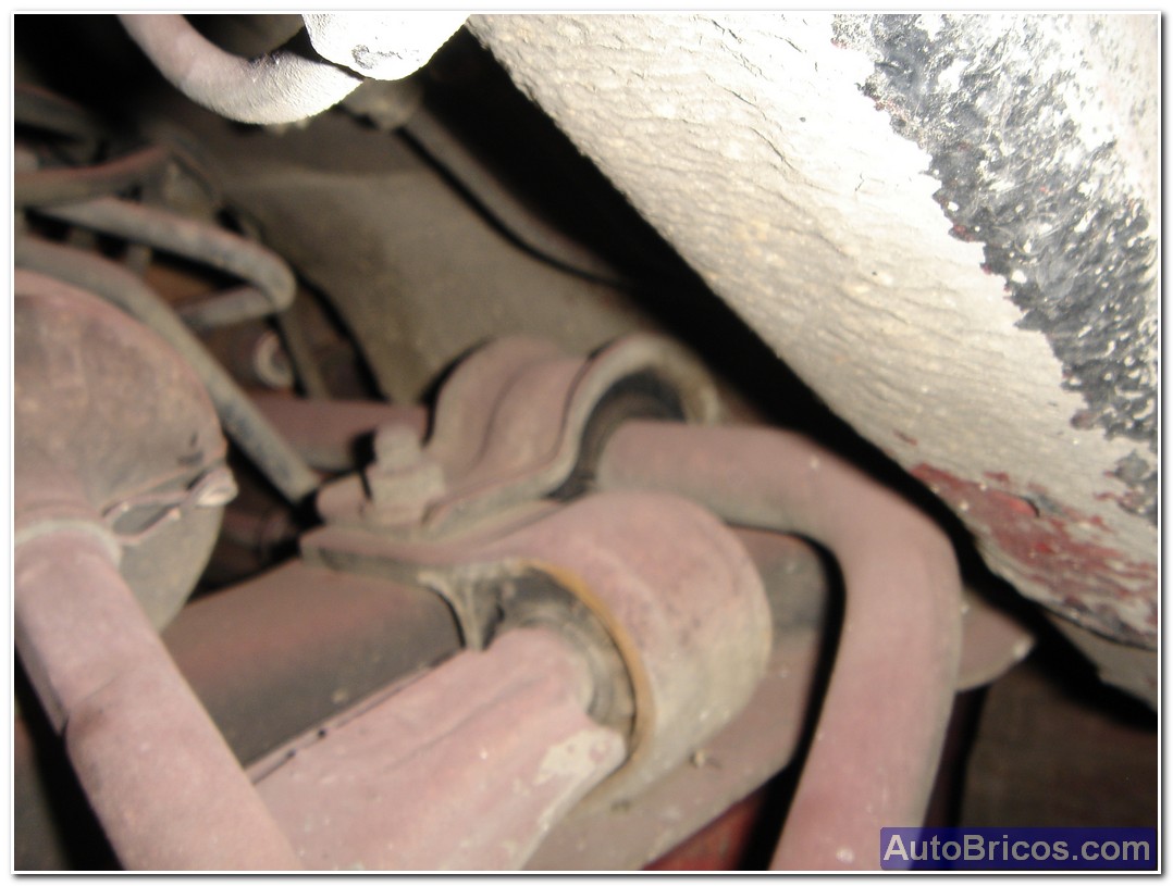
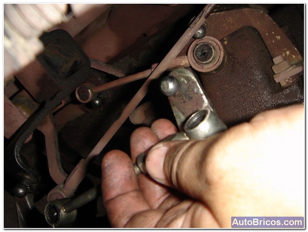
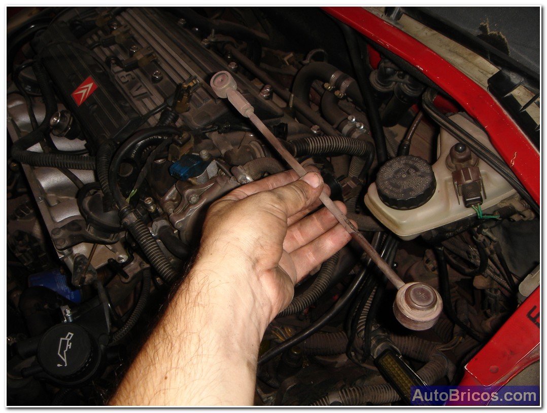
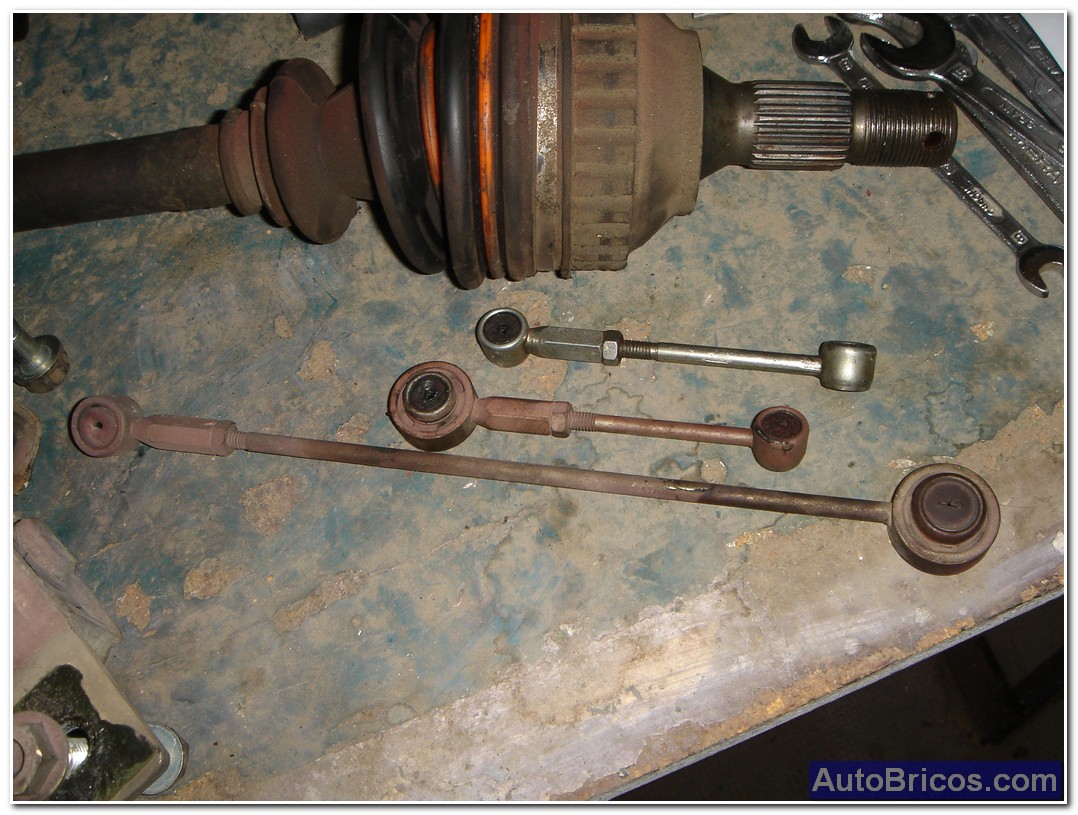
The change rods also need to remove them so they are not bound to change system, and is properly released (two rods are short and long). Typically game and stay caught lever a little loose, so if you are not in good condition when making the new assembly would have to be changed, the improvement is remarkable.
 |
 |
 |
 |
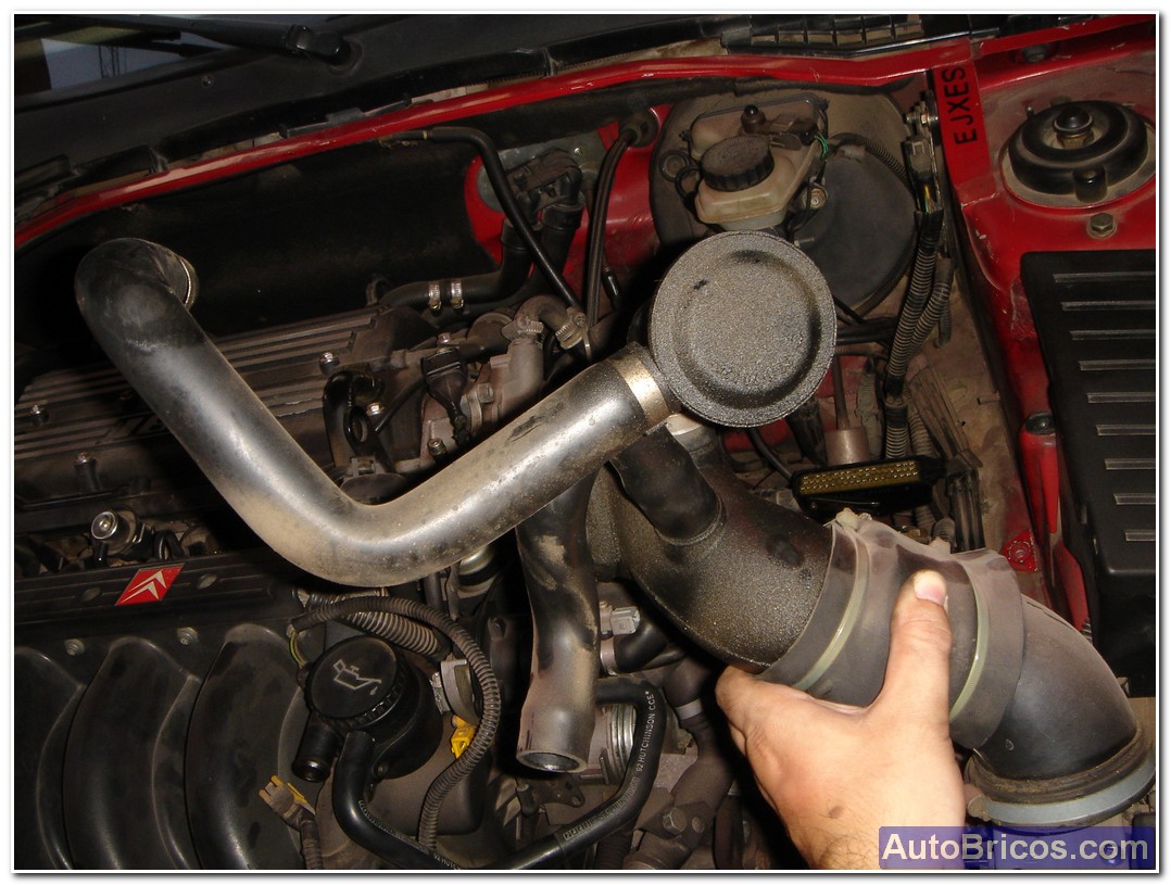
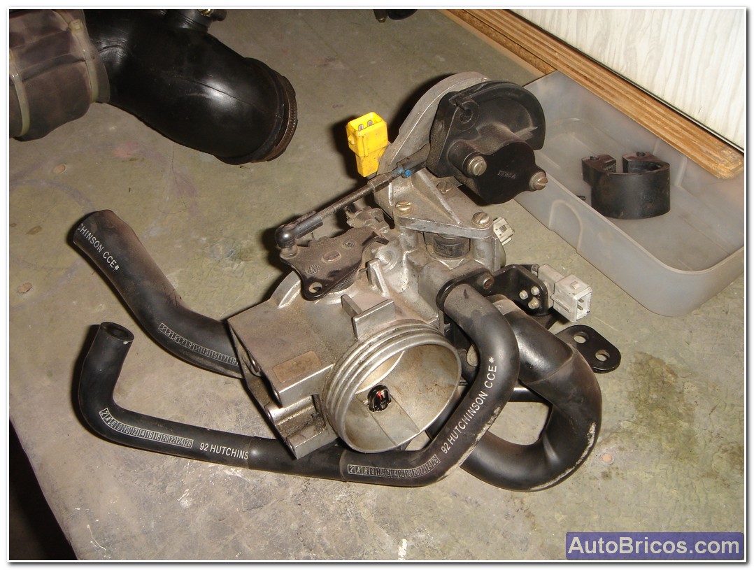
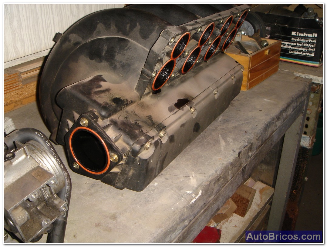
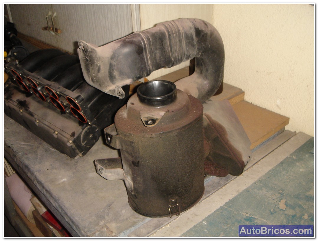
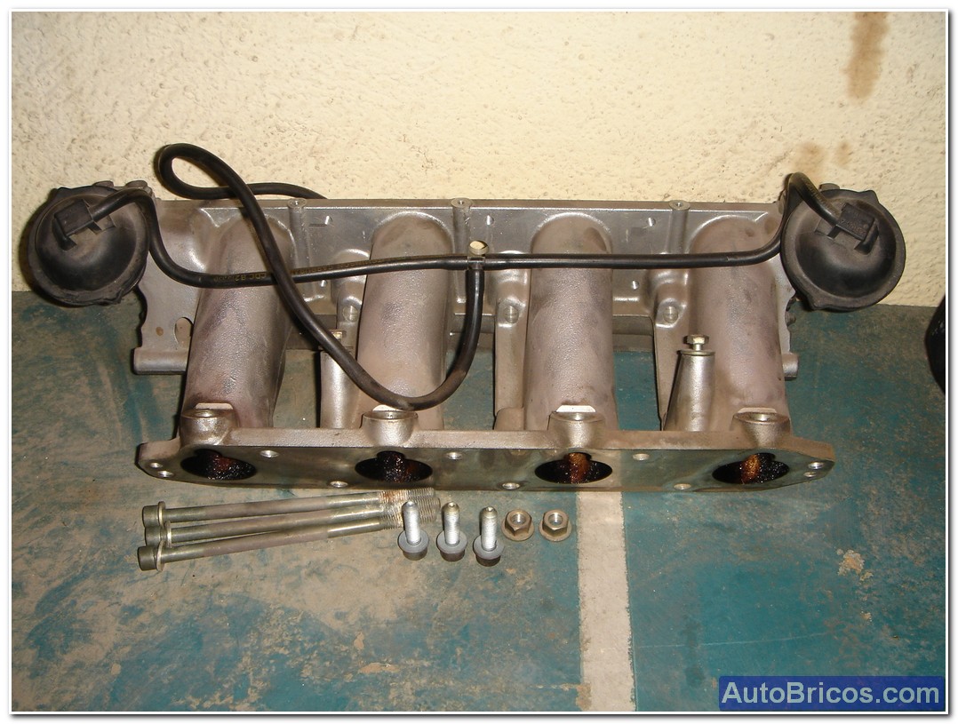
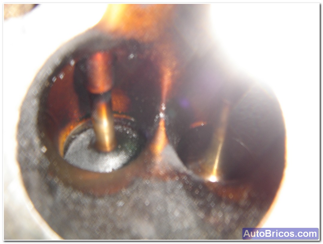
At this point decided to remove the aluminum collector air inlet, which contains the knobs which control the flow of air through the long and short sections of the manifold, and these brackets are opened and closed by two lungs is located on each side of collector, this flow control system input variable is called ACAV. Once removed this collector are aluminum and the stems of the intake valves.
 |
 |
 |
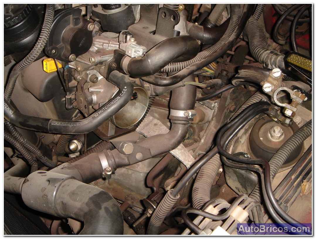
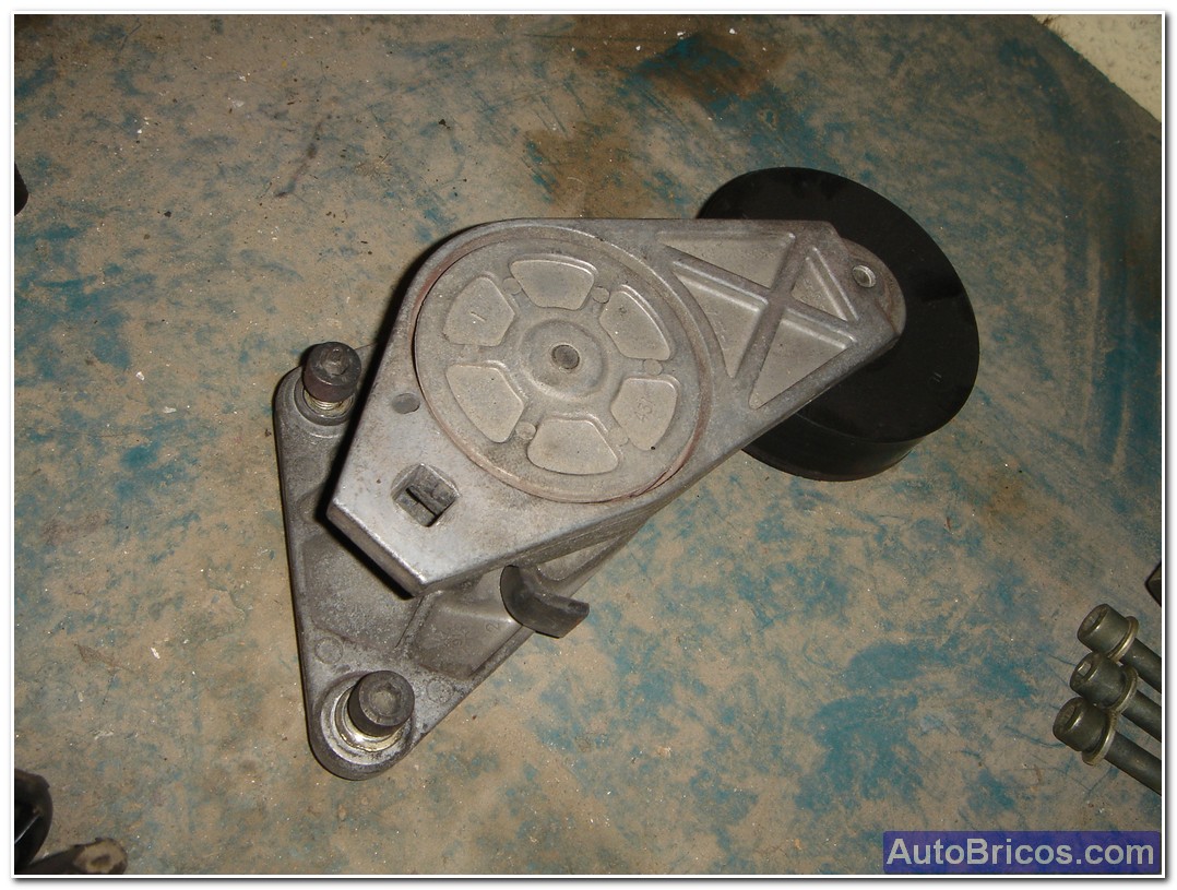
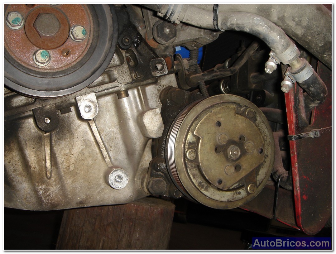
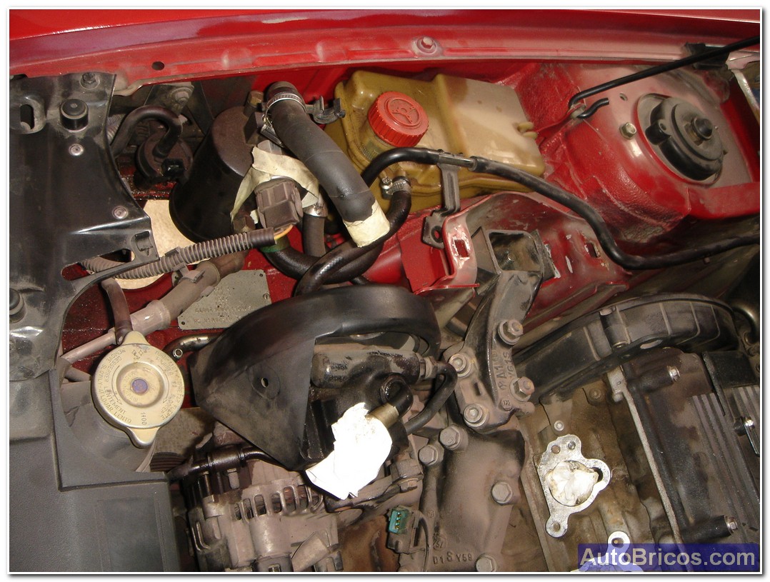
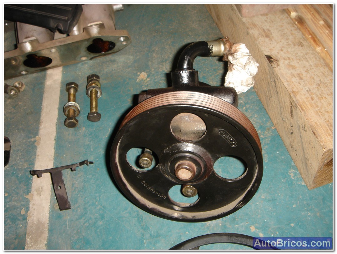
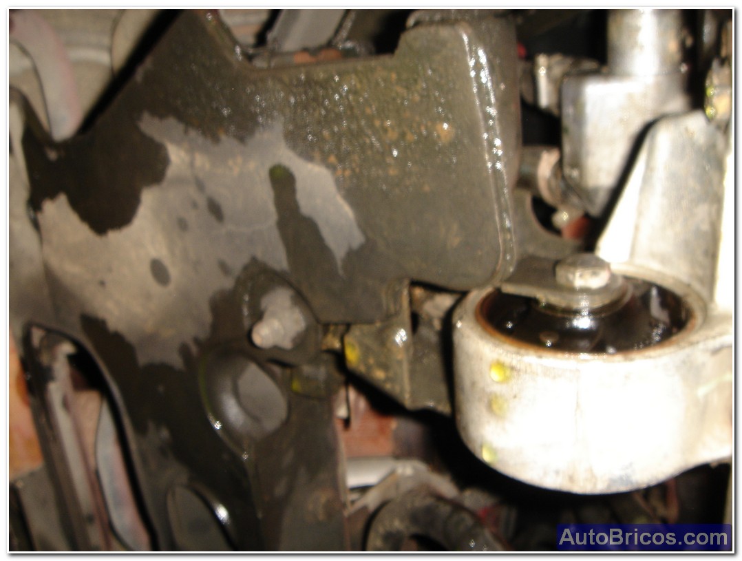
In order to extract the engine, desanclarlo their supports, and for this we have to clear these areas in order to isolate the engine from the chassis. The harness also have to remove for easy operation. Also removed the tensioner to remove the drive belt.
 |
 |
 |
 |
 |
 |
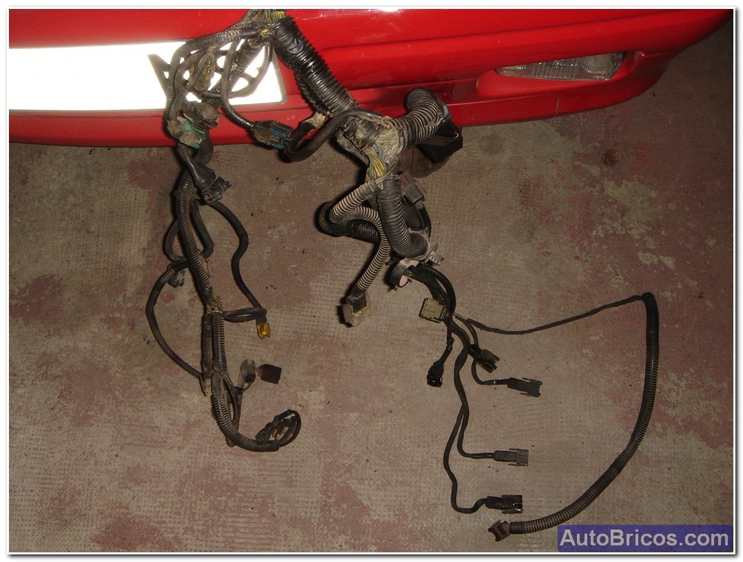
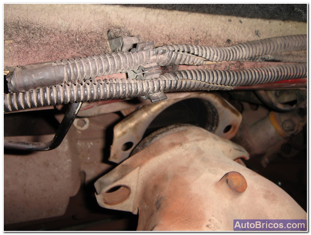
Here we see the wire harness, threw it up to trouble less.
 |
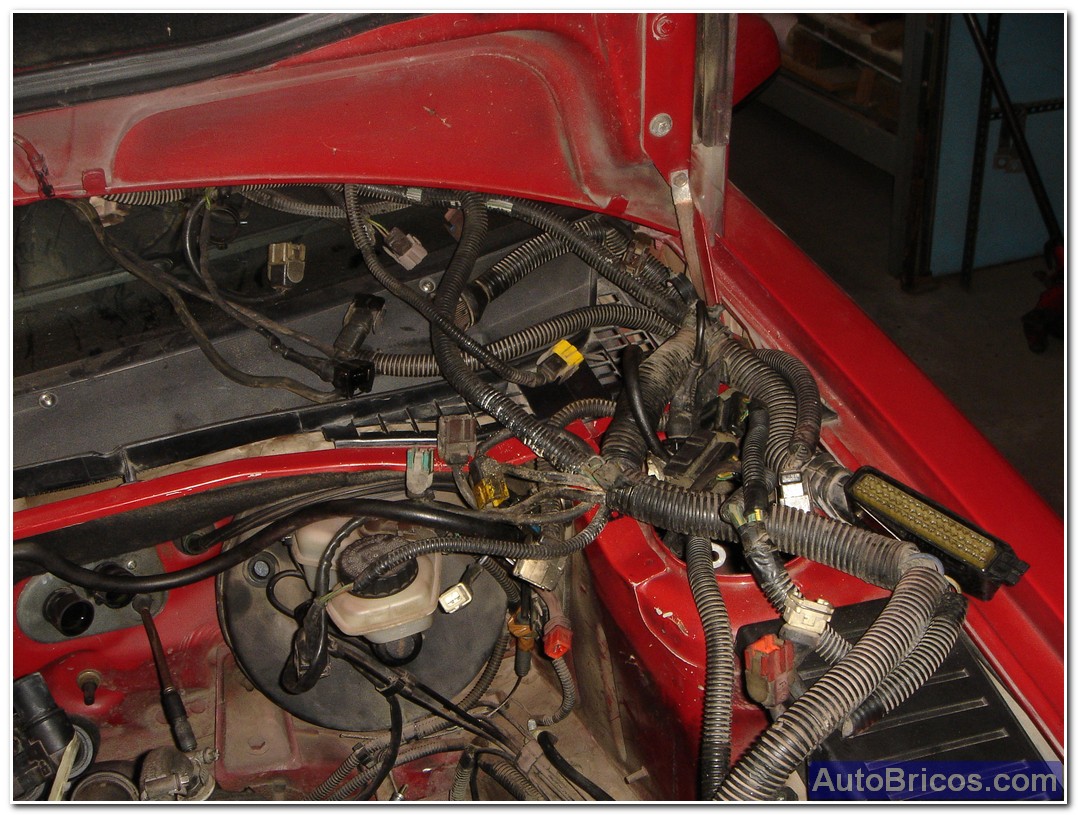 |
Here we see the wire harness, threw it up to trouble less.
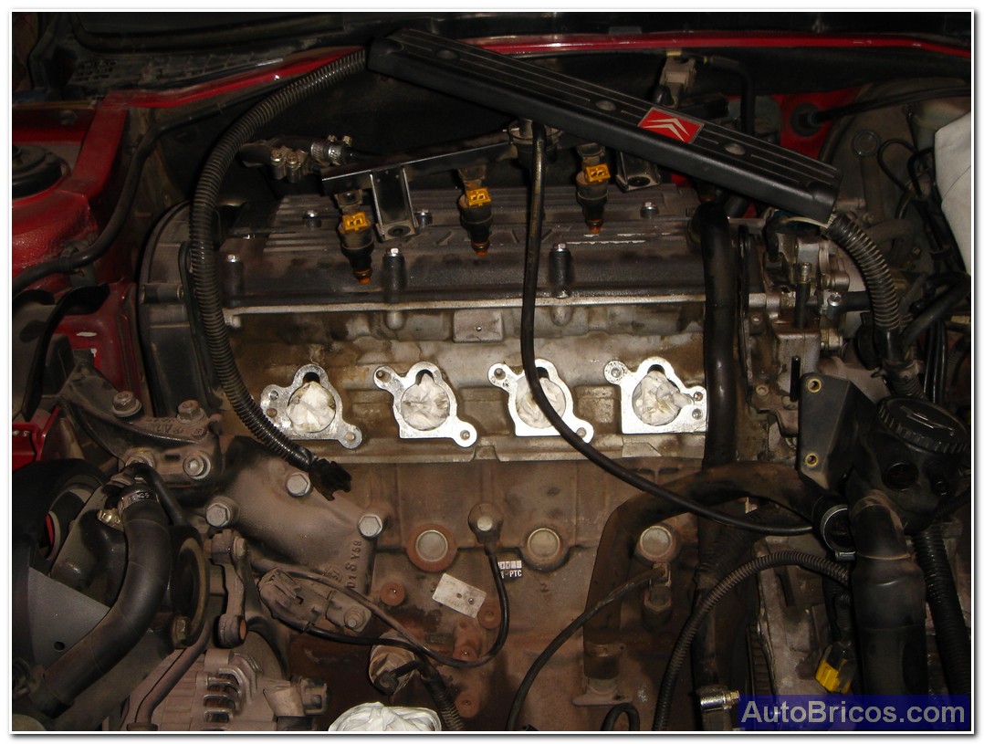
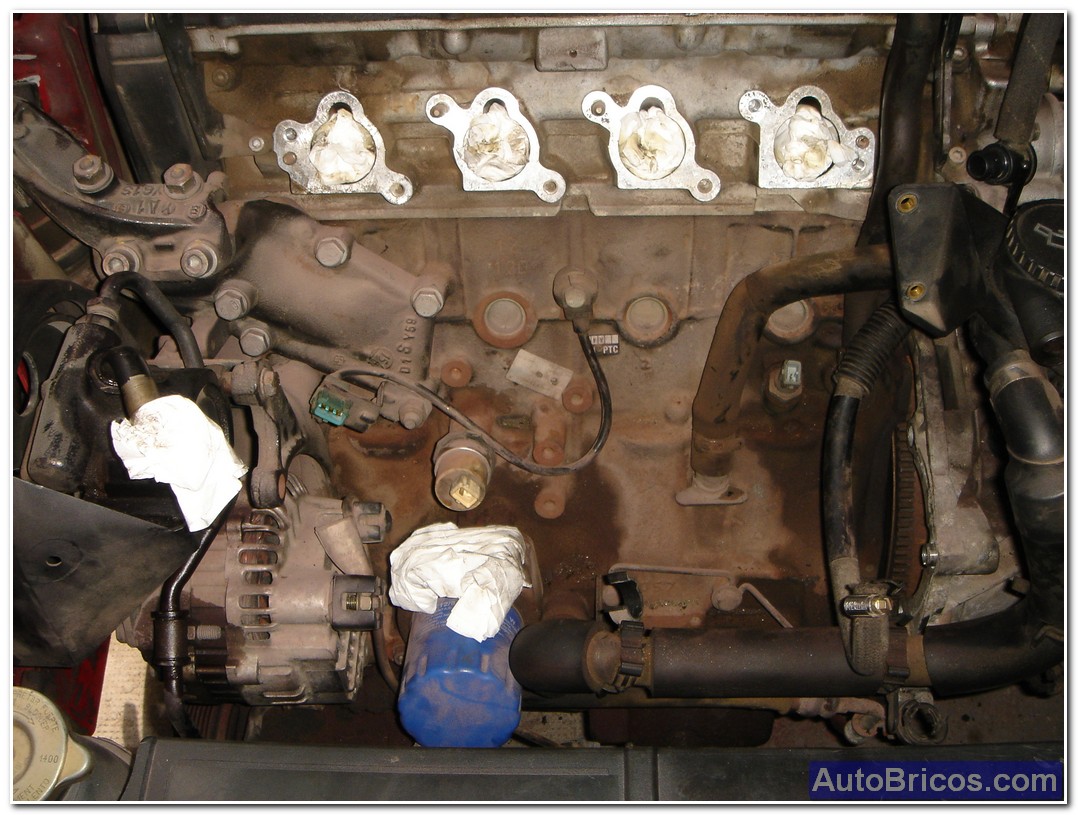
Once cleared areas, plug the holes machined advise collectors and some ducts to prevent dirt to the circuit:
 |
 |
 |
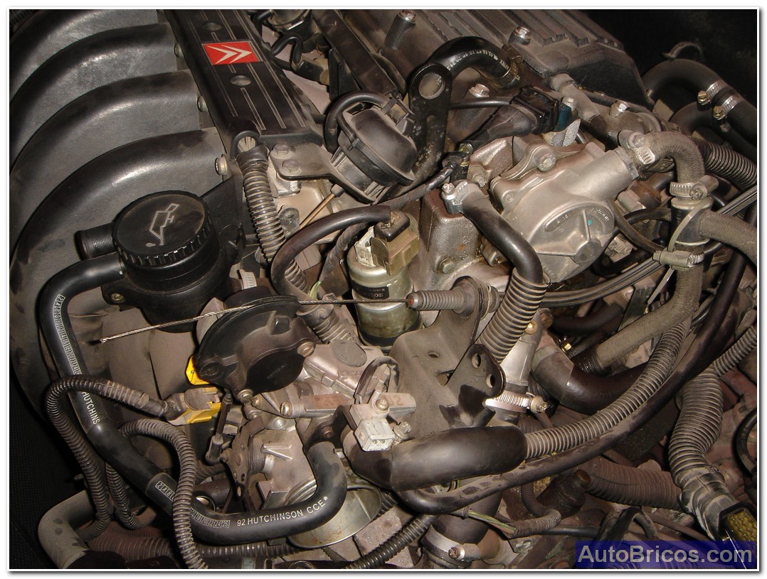
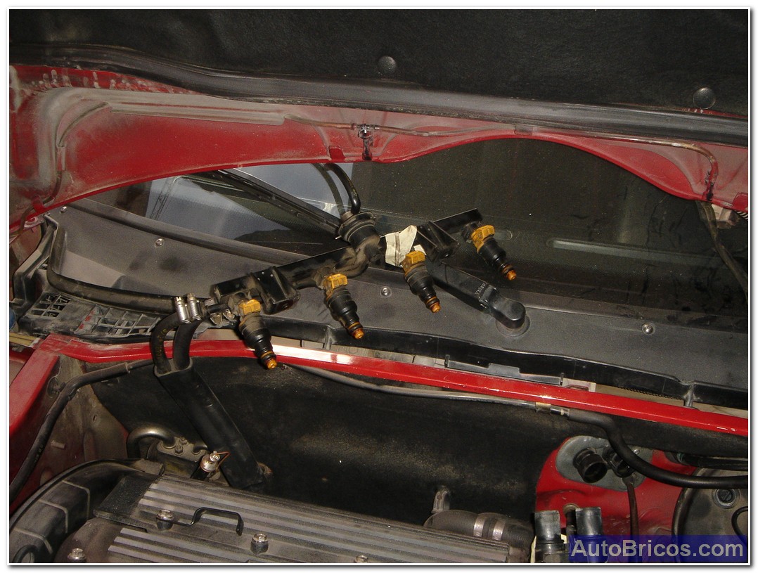
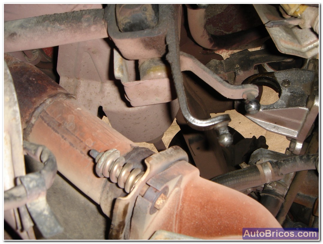
We can ramp injectors away to not disturb us during engine removal. Desacoplaremos also the 2 screws of the patella exhaust manifold, and we will draw the two lower hoses that go from the radiator to the rear aluminum hopper motor.
 |
 |
 |
 |
 |
 |
 |
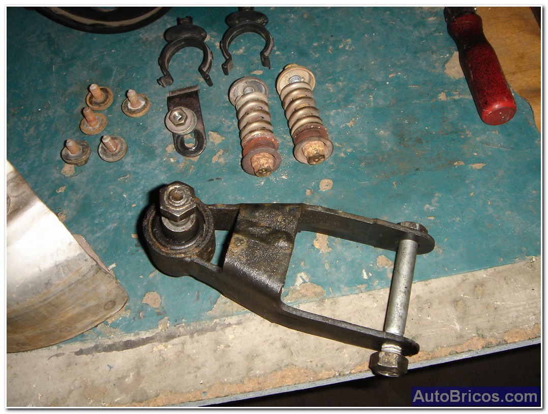 |
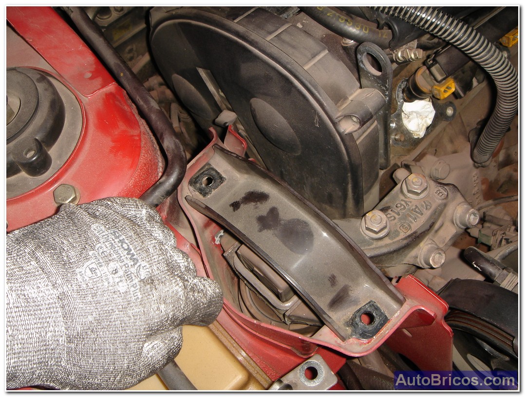
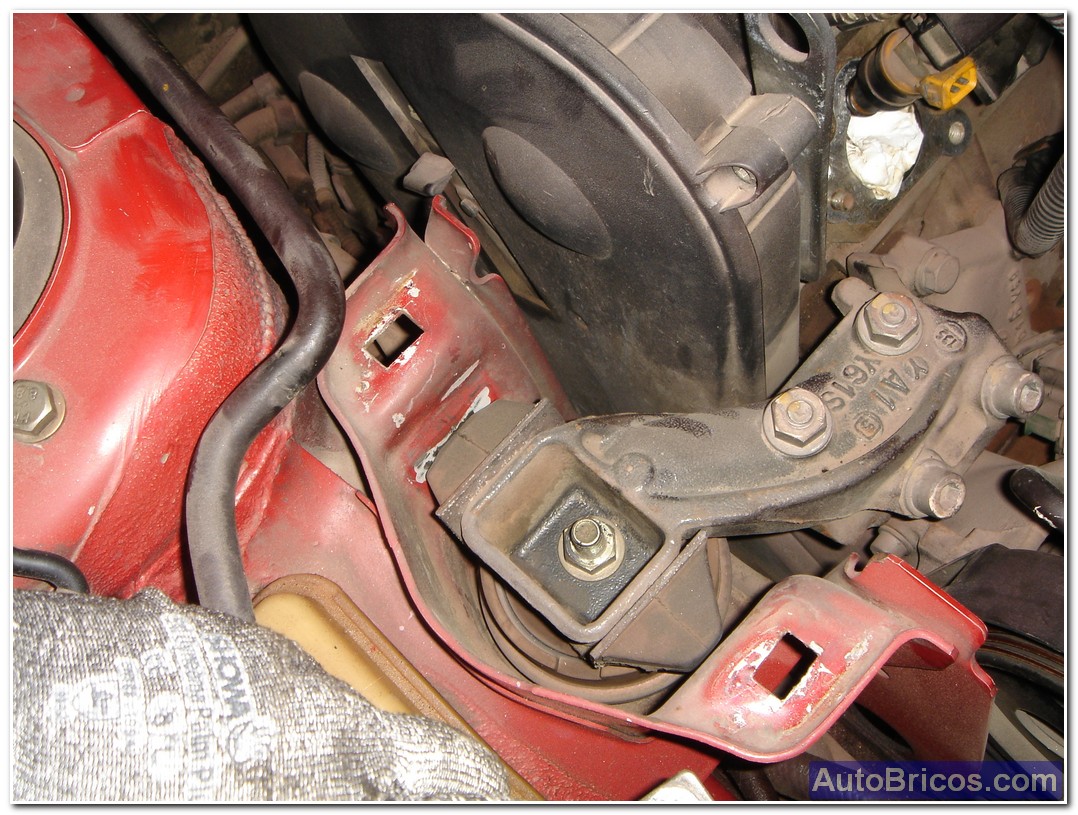
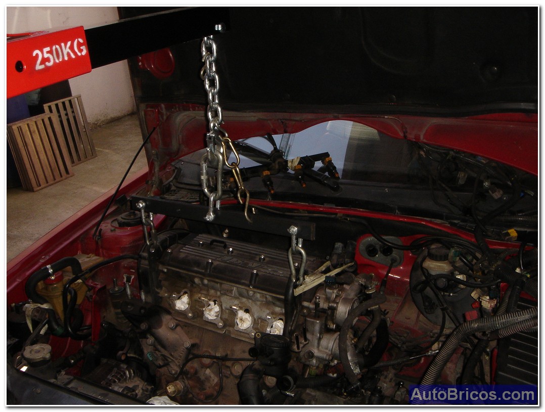
Finally, very carefully, we can begin to remove the engine, using a workshop hoist. For motor movements clearance will remove both solid iron (arm) of the right support as the bowl support of change that will allow us to swing the engine better and we avoid problems, the peculiarity of this extraction is not necessary to remove the front, you have to be careful with the oil filter that does not rub against the radiator, but the engine comes also with no problems.
 |
| Tweet |